 |
| Concept Sketches for Various Structure Designs. |
The biggest complication with projection mapping, is also what makes it an interesting technique. It allows you to essentially create negative space within the projected surface, therefor manipulating the surface without doing so at all. This poses problems however when adjusting the angle from which the surface is viewed, if you imagine a large transparent box with a smaller box levitating inside, the smaller can be viewed from any angle and will remain fixed from from the viewer perspective. When implementing this effect with projection mapping however and projecting the smaller box onto the surface of the larger, not only will the image not rotate when the viewer moves around the object, but when viewing from a corner not aligned with the projection the faces will be aligned incorrectly and will not make sense within their given space.

To this end the corner was the only reasonable option. All would view it from the same angle. However this had been done, it was very similar to the projection mapping videos we had already seen. It was our desire to develop the idea and what could be done with the technique, this is a core principle of the BCT dept and important in development.
It was James who initially told us to find a way to over come the corner issue. He suggested we move past what had already been done by bringing the installation out into the centre of the room. The biggest allure of this for me was creating a space that engaged people as soon as they walked into the room, and from wherever they may be within the room. There would be much more scope involved.
To overcome this we decided to run two projectors from either side of the construct. We would need to run the projected images onto opposite corners, meaning each projector would handle two sides of the canvas each and share the tops via the mapping process. Our use of negative space is slightly hindered with the larger faces, but the tradeoff for the 360 degree interactivity far outweighs the handicap. The geometric canvas would need to:
- Run from point to point on a 45 degree angle to appropriate each projector.
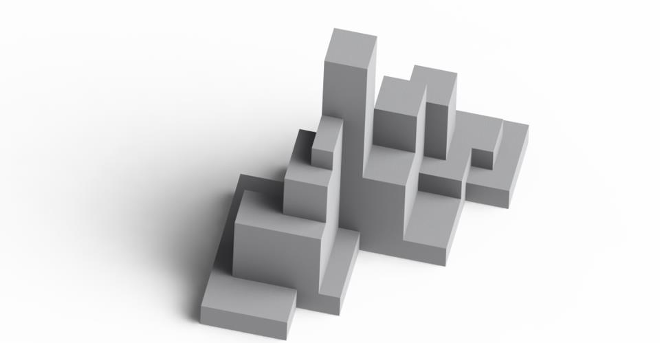
- Be essentially pyramid shaped -wide at the base tapering with height. Any section overhanging the section below would cause drop shadow, and cut off an are from the projector.
- Be diamond shaped when seen from above. Any jutting blocks or 'peninsulas' would again prevent the projected image from reaching the surface behind.
We came up with Lego constructs to quickly and easily come up with a shape. It also allowed us to implement standardized units which would come in handy later with the mapping and net building procedures.


Afterwards Chris Starkey created several 3d CAD drawings, which allowed us to finally see what the structure would look like (if not an understanding of how big it would be). Several slight adjustments were made to the configuration. The first big hurdle was now conquered, we could move onto several different aspects of production that relied on an understanding of the structure itself to move forward.


No comments:
Post a Comment